As wind‑energy deployment accelerates globally, the logistics of transporting major turbine components—particularly blades, towers, and nacelles—have become increasingly complex. Drawing on Gard’s claims experience, this article explores the most common causes of damage during the carriage of turbine parts, highlighting key risks and practical steps owners and operators can take to reduce exposure.


Published 13 April 2026
According to the International Energy Agency (IEA), turbine sizes have grown substantially, with taller hub heights and larger rotor diameters now standard. This underscores the need for robust heavy‑lift capability, dedicated project‑cargo vessels, and more streamlined permitting and development processes. Although multipurpose vessels are generally best suited for wind‑component transport, the growing use of bulk carriers for these shipments demands closer risk evaluation and tighter operational controls to ensure safe carriage.
The article summary
• The rapid growth in wind-energy projects and turbine size is increasing demand for the sea transport of oversized components such as blades, towers and nacelles.
• Transporting wind turbine cargo presents significant technical and operational challenges, particularly where non-specialised vessels are used.
• Common incidents include hatch cover damage, lashing failures, cargo movement in heavy weather, fire during cargo operations and handling damage during loading/discharge.
• Many losses are linked to inadequate engineering assessments, poor structural design of transport frames, insufficient securing arrangements and lack of oversight during loading.
• Heavy weather and voyage planning remain critical risk factors, as dynamic forces can exceed the design limits of securing systems and vessel structures.
Clear contractual responsibilities, proper surveyor involvement, strong engineering controls and disciplined cargo handling procedures are essential to reduce risk and prevent costly claims.
Gard has significant claim experience with how technical and operational vulnerabilities manifest. The following case studies provide examples of typical failure modes, underpinning the broader issues discussed in the subsequent section.
Case Studies
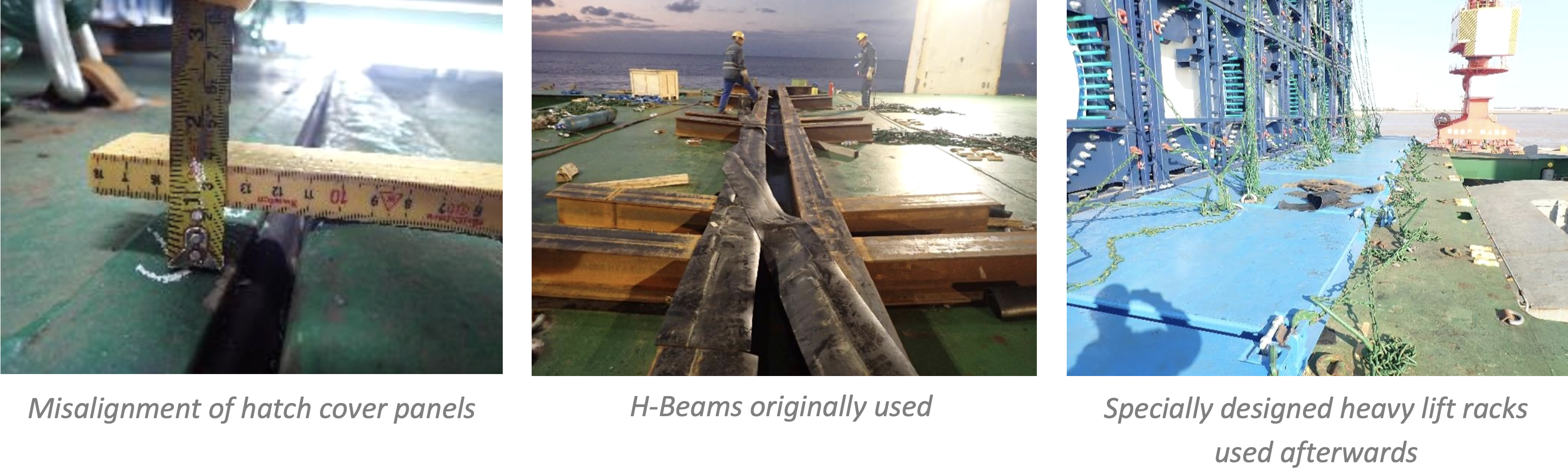
Case Study 1 – Indentation of hatch covers during loading
During cargo operations at a port in China, H-beams were initially utilized to distribute the weight of wind turbine blades across the hatch covers. However, this method proved inadequate, resulting in approximately 100mm indentation on the hatch cover top and a vertical misalignment between adjacent panels. All previously loaded cargo had to be discharged to facilitate a thorough assessment by a Class surveyor. Once the surveyor confirmed that no permanent damage had occurred and the vessel’s integrity was intact, owners and charterers collaborated to rework the stowage plan. The inadequate H-beams were replaced with specialized heavy-lift platforms. These racks were engineered to rest directly on container seats and are secured via twist locks, ensuring the load is transferred to the vessel's reinforced structural points rather than the hatch cover plating.
In another similar case, damage to the hatch cover panels had to be repaired to the satisfaction of the Classification Society.
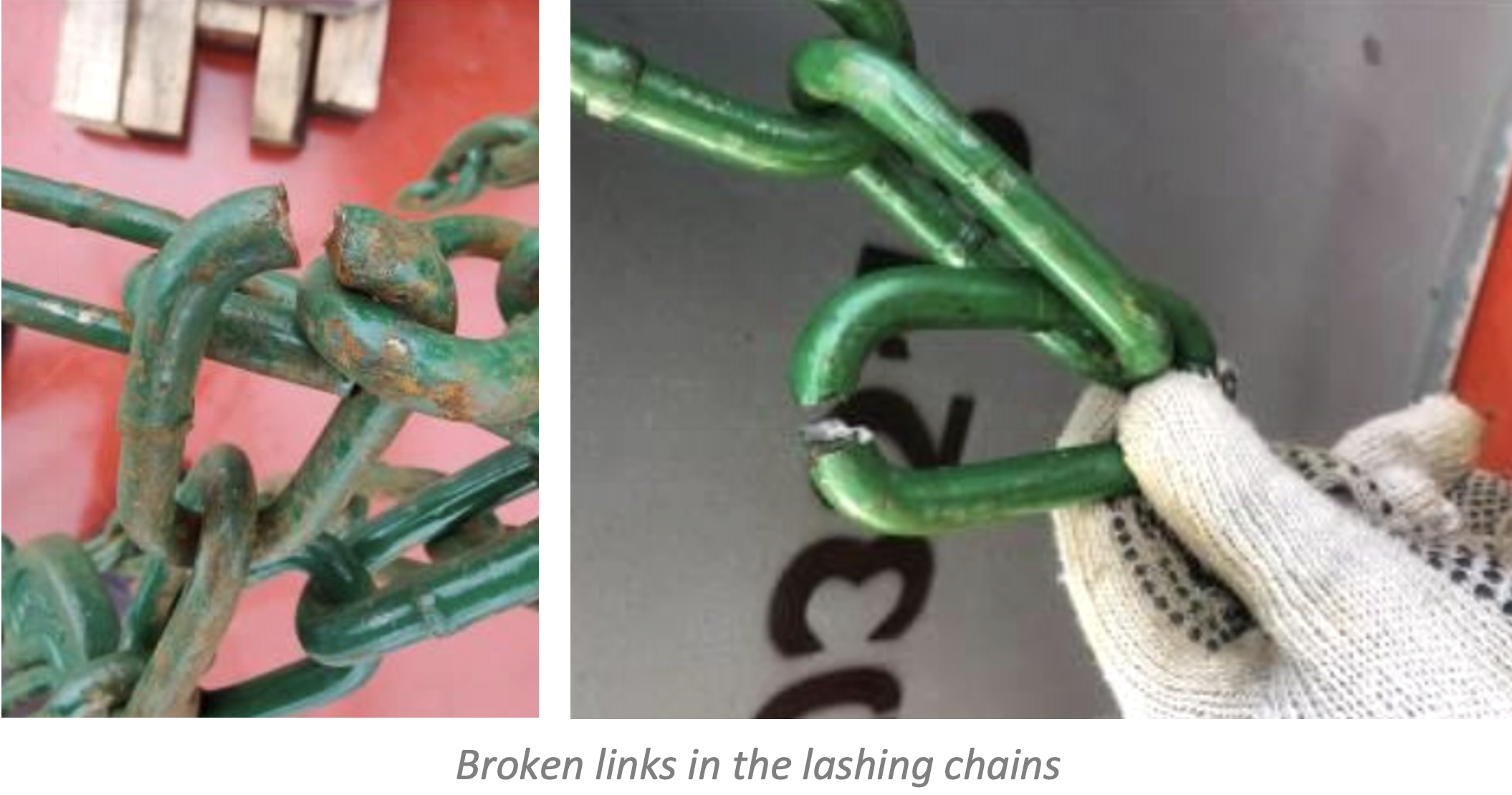
Case Study 2 – Sub-standard lashing material
A few days into the voyage, the crew identified multiple broken links across several lashing chains. This led to an unscheduled stop at an intermediate port for full replacement of the damaged gear. Preliminary findings indicate the lashing certificates provided at the load port did not accurately reflect the breaking strength of the chains. There was also no evidence to show what strength of lashings were required for the cargo.
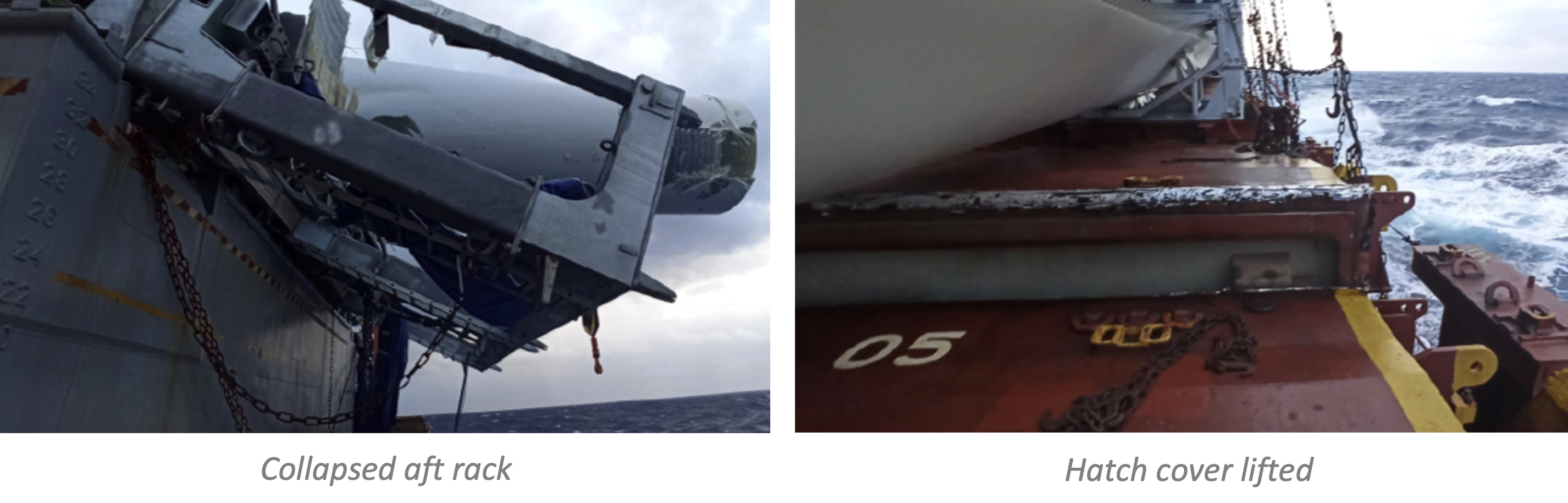
Case Study 3 – Movement of cargo and damage to hatch covers in heavy weather
The vessel departed China after loading 27 wind turbine blades in a "long-stack" configuration, with 16 blades secured in the forward rack and 11 in the aft rack. After transiting the Suez Canal, the vessel encountered heavy weather, with wave heights exceeding 5 meters and winds reaching Beaufort Force 7/8. These conditions induced rolling of up to 10 degrees. The resultant dynamic forces caused the center and forward racks to tilt toward the bow, while the aft rack collapsed toward the stern. The magnitude of these forces exceeded the design capacity of the hatch cover cleats, leading to significant damage and the lifting of the hatch covers. The ship diverted for temporary securing and later underwent Class supervised permanent repairs, including replacement of three hatch panels.
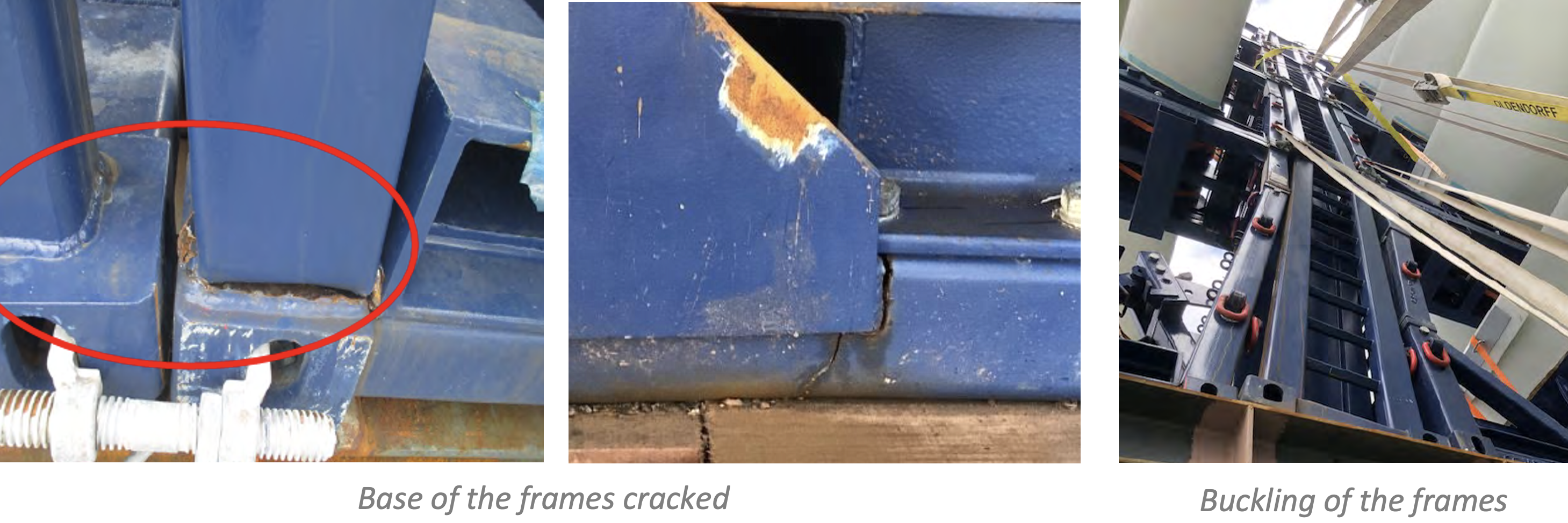
Case Study 4 – Damage to the frames transporting blades
During a voyage to a U.S. port, the crew noticed that several frames carrying wind turbine blades had buckled. Following discussions with the owners, the decision was taken to proceed to a port for emergency reinforcement works. These frames were specifically designed for the transport of wind turbine blades, with each unit consisting of two components: a "root frame" to support the base of the blade and a "tip" or "end frame" to support the blade's extremity. Investigation identified a two-fold root cause for the failure. First, incorrect installation led to a misalignment of the blades within the frames. Second, the 3x4 matrix provided inadequate structural support. Combined, these factors created a concentration of stress at the frame joints that propagated upward. The resulting failure damaged six transport frames and caused minor impact and coating damage to seventeen blades, ultimately forcing the vessel to divert for immediate repairs.
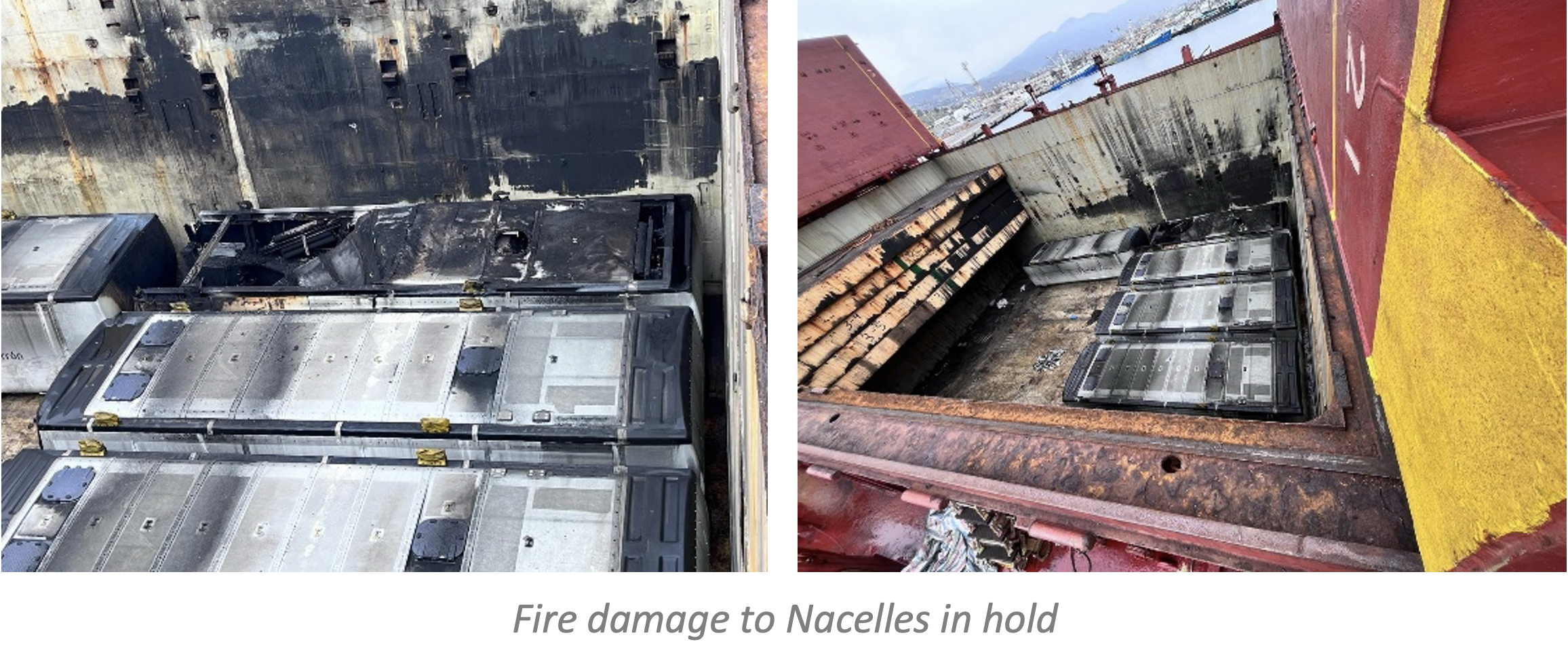
Case Study 5 – Fire during discharging operations
During discharging operations, a fire broke out in one of the holds. Shore workers began flame-cutting cargo securing arrangements without authorization by the crew or proper fire precautions in place. This allowed sparks to fall into the lower hold, initiating a fire. In response, firefighting measures were taken, including the release of the CO2 system into the hold and the mobilization of two tugs to assist. The resulting fire damage was primarily sustained by nacelles stowed in the hold.
Although fire‑damaged cargo may sometimes be repaired, this is not the case in every instance. In another similar case, the cargo receiver determined that the extent of heat and soot damage to the nacelle, together with contamination from hydrochloric acid vapours produced by burning PVC, made repair economically unviable. In this case, the hotwork was carried out by the ship’s crew.
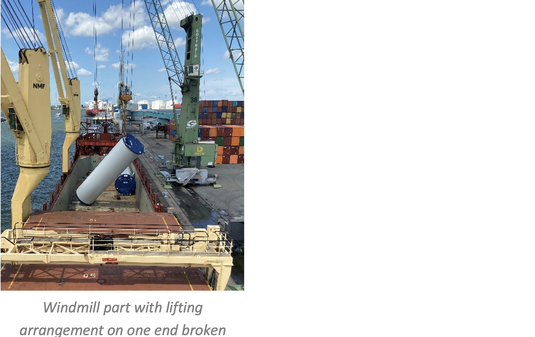
Case Study 6 – Tandem‑Lift Breakdown
During discharge operations, a heavy wind turbine component was being lifted from the upper hold using the vessel’s own cargo cranes in a tandem‑lift configuration. While hoisting, the lifting arrangement on one side came loose, causing the component to fall back into the hold and land on the installed tween‑deck pontoons. The impact resulted in severe deformation of three pontoons and additional indentations to the hold side bulkheads. A subsequent joint survey confirmed the structural damage and the need for repair and renewal of the affected tween‑deck sections.
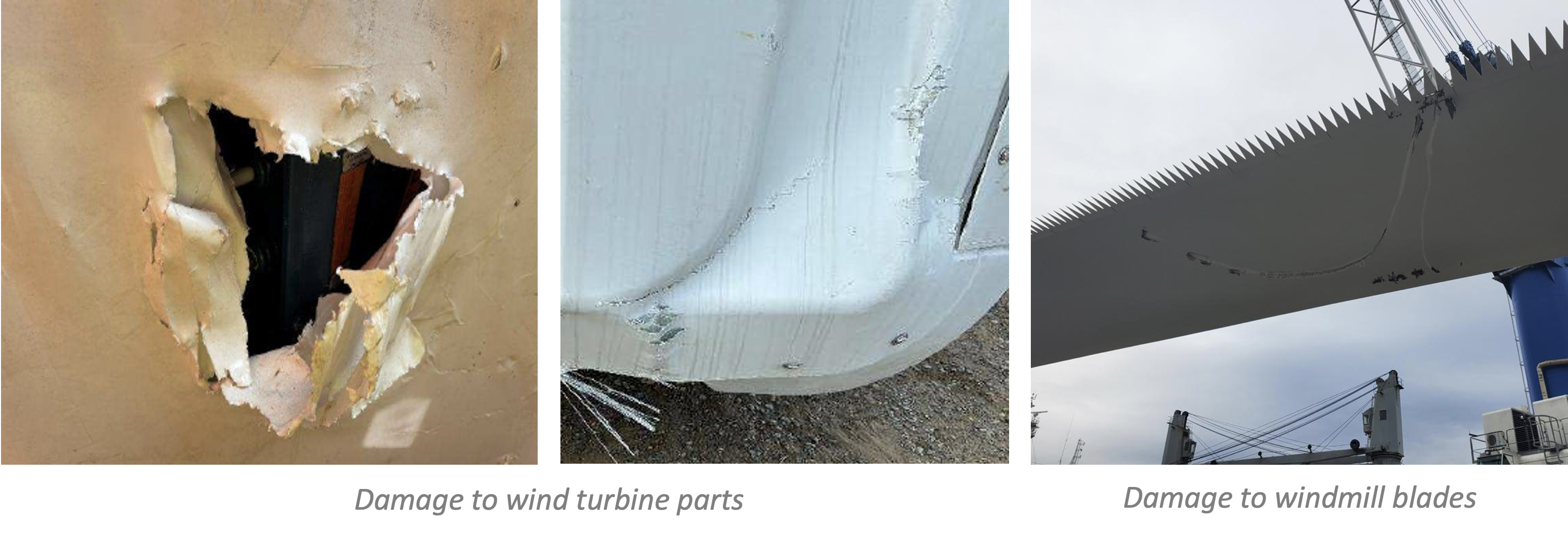
Case Study 7 – Damage during discharge
During discharge operations, several blades and wind turbine parts sustained physical damage due to a combination of poor handling and communication failures. Investigation revealed that the stevedore team failed to maintain proper control of tag lines, leading to "uncontrolled swings" where the cargo struck nearby structural obstacles. Furthermore, allegations were made regarding surface "scratch damage" caused by improper contact with lashing materials during the removal process. A critical contributing factor was that the crane operator’s line of sight was completely obstructed; he was unable to visually monitor the cargo during the lift.
Key issues
The case studies outlined above highlight a pattern of technical and operational vulnerabilities in the sea transportation of wind‑energy components. While only a few examples are presented here, Gard has been involved in several similar incidents. When assessed collectively, these incidents reveal several critical risk areas that require stronger oversight, clearer allocation of responsibility, and more robust engineering and operational controls.
Lashings
Lashings are among the most critical safety components in the transport of wind‑energy cargoes. In practice, lashing materials and securing operations are often supplied and executed by charterer‑appointed stevedores, which can limit the vessel owner’s direct oversight of procurement and quality control. As a result, there is a risk that certified lashing materials may not meet the actual strength requirements for the voyage. Several incidents have also shown that vessels did not carry sufficient spare lashings to replace damaged gear during the voyage, increasing the risk of escalation once failures were detected at sea.
Fire safety
The unauthorized use of hot work by shore personnel - without proper permits, fire‑watch arrangements, or crew notification, represents a significant and recurring risk. These events can escalate rapidly, often necessitating the release of fixed CO₂ systems and the mobilization of external firefighting assistance. The consequences are frequently severe, particularly where high‑value components such as nacelles are exposed to fire, heat, or smoke damage.
Insufficient engineering controls, structural design & installation quality
Several incidents were linked to shortcomings in engineering discipline and execution. These included missing or inadequate acceleration assessments, improvised load‑spreading arrangements that overstresses hatch covers, and transport frames that were not structurally suited to the actual loading configuration.
Installation quality further compounded these issues. Misaligned blade‑transport frames created uneven load paths and localized stress concentrations, ultimately resulting in structural deformation and blade damage. Taken together, these cases point to gaps in engineering verification, load‑path assessment and installation controls. Furthermore, ship’s crew often lack the technical means to verify the structural integrity of the transport frames, such as the ones showed in Case Study 4. Such knowledge usually remains with the shipper and the charterer, leaving the crew with limited oversight during loading.
Weather-induced failures
The carriage of large, high‑surface‑area components such as turbine blades can expose the vessels to extreme dynamic forces in heavy weather. Many of the failures observed fall into the category of design‑capacity overloads, where rolling and acceleration forces exceed the structural limits of hatch‑cover cleats, securing arrangements, or supporting frames.
Once cargo movement occurs, these failures often develop into a chain reaction, compromising both the cargo and the vessel’s primary sea‑keeping integrity. Experience from heavy‑weather incidents, including container stack collapses, demonstrates that the absence of defined wind, wave, and acceleration thresholds during voyage planning is a key factor exposing vessels to damaging conditions.
Cargo handling by stevedores
Damage during loading and discharge remains a significant risk, particularly where visibility, communication and control are compromised. In several cases, blades were damaged due to rough handling by stevedores, inadequate control of tag lines, contact with fixed obstacles and movement of blades during hoisting or lowering during strong winds. Limited or obstructed crane‑operator visibility further increases the risk of uncontrolled movements.
Navigation bridge visibility
Although not addressed in the case studies above, it is important to highlight bridge visibility requirements. Deck stowage must not compromise SOLAS V/22 bridge visibility requirements or impede safe navigation. Visibility constraints should be assessed at the planning stage. It is worth highlighting that some port states, such as AMSA and USCG, might not recognize Flag State dispensations for breach of SOLAS bridge visibility requirements. Reference can be made to our article ‘The importance of ensuring navigation bridge visibility’ for further details.
Contractual considerations
Clear and well-structured contractual clauses is key to determine how responsibilities, approvals, liabilities and operational controls are allocated during the carriage of wind turbine blades. The following considerations consistently influence outcomes in claim scenarios:
Bills of lading and legal framework
When wind turbine blades are intentionally carried on deck, Members should ensure that the contractual documentation accurately reflects the physical mode of carriage. In such cases, particular attention should be paid to the allocation of responsibility for loading, stowage, securing and discharge operations, especially where multiple parties are involved.
Where blades are carried on deck, the Bill of Lading should clearly record this fact. Failure to expressly identify deck carriage may result in the Hague Visby rules not applying to the contract of carriage, which may not only preclude Owners from various potential defences to cargo claims, but also preclude them from relying on their P&I cover. Experience from prior cases shows that ambiguity in deck‑cargo wording, particularly where the number or identity of units carried on deck is unclear, tends to be construed against the carrier.
Hence, we recommend that the applicable Bills of Lading are claused accordingly, for example as follows:
"(....) OUT OF (...) (PACKAGES / CONTAINERS / BUNDLES / UNITS ETC) SHIPPED ON DECK AT CHARTERERS'/SHIPPER'S/RECEIVERS RISK, RESPONSIBILITY AND EXPENSE AND WITHOUT ANY LIABILITY TO THE VESSEL AND/OR HER OWNERS FOR ANY DELAY AND/OR LOSS OF OR DAMAGE TO CARGO AND/OR SHIP WHATSOEVER AND HOWSOEVER CAUSED."
If Members are held liable for loss or damage to the cargo, despite having claused the Bills of Lading in accordance with the suggested wording, cover will remain in place up to the Hague-Visby limits, always under the condition that the carriage is approved by Class.
Clarity on responsibilities for stow, securing and operational oversight
It is essential that contractual wording clearly assigns responsibility for the engineering of the securing provisions, provision of lashing equipment, removal/disposal of materials, operational supervision, and compliance with Class approved arrangements. Clear delineation of obligations helps avoid disputes when allegations of improper stowage or operational unseaworthiness arise.
Structural modifications, welding and on deck fittings
Pad eyes, stoppers and additional support may have to be installed to facilitate blade carriage. However, it must exclude welding on tank tops or fuel tanks. Contracts should specify responsibility, timing and acceptance criteria for removal, including requirements for Class approved welding procedures and non-destructive testing where appropriate. Any temporary structures should be removed and reinstated, including coating and surface protection before redelivery.
Surveyor engagement and evidence preservation
Contracts should allow for independent surveyor attendance wherever necessary, especially during loading, securing, stow verification, and damage assessments. This protects the evidentiary position on structural condition, compliance with approved securing plans, and the adequacy of stowage. Parallel involvement of qualified loading surveyors or Port Captains ensures operational discipline and reduces the risk of later disputes regarding execution. Agreement between the parties on the costs would also be worthwhile.
Key recommendations
Define responsibilities clearly in contracts. Ensure charterparties and related contracts clearly allocate responsibility for the engineering and approval of securing arrangements, provision and quality of lashing equipment, appointment of surveyors, and reinstatement of vessel structures after discharge. Bills of lading should also expressly state when windmill parts are carried on deck.
Use expert surveyors and notify insurers. Appoint an experienced, independent marine surveyor to oversee the entire loading and securing process. Consider notifying insurers before carrying wind turbine components on deck of non-specialised vessels as it can be considered as an alteration of risk.
Follow Cargo Securing Manual (CSM) and involve Class early. Ensure all securing follows the approved Cargo Securing Manual. For bulk carriers, early engagement with a Classification Society is essential. Class societies do issue approvals after reviewing and verifying certain aspects, such as:
Strength assessments of decks and hatch covers on which cargo is to be stowed.
Verification of connection points, including cargo‑securing arrangements, bed frames, and their attachments to hatch covers or deck structures.
Assessment of loads and accelerations, taking into account vessel characteristics, cargo weight, centre of gravity, and expected dynamic forces.
Verify lashing equipment quality. Use only verified lashing and securing gear with proper markings and documentation. Reject any equipment showing signs of wear or lacking certification, and maintain an adequate stock of spare lashing materials onboard.
Carry out engineering assessments. Each voyage should be supported by a cargo‑specific engineering assessment reflecting the vessel’s characteristics and route to be taken. Motion and acceleration calculations should consider hatch cover cleats, expected sea conditions and strength of the lashings. The design and stiffness of blade racks, structural integrity of transport frames, maximum permissible height of stow, load transfer points and acceptable deflections should be verified, and OEM transport requirements considered where applicable. Hatch cover maintenance, including bearing pads, should also be reviewed.
Ensure careful cargo handling. Use experienced stevedores and crane operators with approved lifting plans. Ship’s crew should document any rough or incorrect handling, issue protests where appropriate, and inform charterers without delay.
Hot work and fire prevention. Limit hot work near cargo and ensure it is managed under a formal permit‑to‑work system with a cargo‑specific risk assessment. Where structural modifications or additional securing points are required, these should be completed before loading and approved by Class.
Check visibility and stability. Deck stowage must comply with SOLAS V/22 bridge visibility requirements and there must be calculations done to support this. If long blades obstruct sightlines, the stowage plan should be modified rather than relying on Flag State dispensations. Vessel stability, including GM, trim, and wind-heel calculations, must be assessed to ensure adequate margins remain with the deck cargo in place.
Plan voyages conservatively. Avoid heavy weather where possible, and use cautious route planning, especially in known high-risk areas and seasons.
Monitor cargo throughout the voyage. Conduct regular lashing inspections (when safe), keep photographic records, and document/report any issues promptly.
Relevant Gard articles
Related Articles


Gard is a member of